Powering the RPi
Table of contents
Update: 08.05.2021
In order to keep the information on one side, I updated and corrected some sections and pictures.
I also did a Part 2, which you can read here.
Additional information about some missing models is added there.
Power to the Pi
In order to get a stable system you need a good power supply. With the RPi4 the new standard power supply provides 5.1 V and up to 3 A.
Older models had a PSU with 5.0 V.
Since not all voltages on the board are 5 V, several voltages for the processor, the memory etc. are generated.
With the over_voltage feature you can adjust some voltages, mainly VDD_CORE for the processor and V_DDR for memory.
To get higher clock speeds, sometimes you need to increase the voltage.
More is better
But sometimes the voltage you can get with the highest over_voltage setting is not enough. For the RPi4 VDD_CORE 1.1 V is the limit, while it’s 1.4 V for RPi3 and lower.
To get an even higher VDD_CORE you need to perform a voltmod.
Raspberry Pi 1 Model B
On the original Model B you could bypass the VDD_CORE generated by the Pi itself and inject your own voltage.
The inductor L5 on the backside of the board needs to be removed. Now you can use C16 as a point to supply an external voltage directly into the core.1


The schematics for the RPi1:

Raspberry Pi 1 Model B+
With the redesign of the PCB I don’t know, if you still can easily hook up an external power board directly to the processor.
Looking at the PCB there are similarities, maybe we can improvise. It looks like the inductor L5 is now called L3 and the point, where you can inject your voltage on the front is now called C21.


Raspberry Pi 2 Model B v1.1/1.2
It is possible to trick the integrated circuit of the RPi2 to generate more voltage itself.
Therefore we use the feedback pin of the circuit, which contols the voltage of the VDD_CORE that the voltage is too low.
For this you need to change the voltage divider, to modify the reference voltage for VDD_CORE.
The resistors R55 and R56 need to be changed to 100 Ohm (R55) and 680 Ohm (R56). This sets the reference voltage from about 1.225 V to 1.4 V.
You gain about 200 mV.2 This should bring enough room for higher clocks.

The second option it injecting an external voltage. For more information look down below at the RPi3, because this method was tested on this model first…even if the model was released later on.

The schematics for the RPi2:

Raspberry Pi 3 Model B v1.2
Like the RPi2B with this model you also have two possible ways to get more voltage to the processor.
Trick it with a modified voltage divider to gain about 200 mV or inject your external voltage.
The capacitor and inductors are labeled the same and serve the same purpose, even if the layout of the PCB is slightly different.
For the modification of the voltage divider you need the same resistored mentioned above.
R55 needs to be 100 Ohm and R56 680 Ohm.
If you need more power, search for C163, which is the point to hook up your external voltage.3


Looking at the schematics, removing the L3 inductor is also recommended.

My best Raspberry Pi 3 B was clocked at x264-stable 1,550 MHz with temperatures about -35 °C and a VDD_CORE of 1.8 V which I bypassed via C163 from the 1.8 V rail of the RPi itself.
After almost 9 hours of benchmarking, condensation turned into ice and the RPi finished the x264-benchmark in 8h 55m 15.647s.
With this special treatment I was able to gain about 150 MHz and killed all USB-Ports and the Ethernet, too.
I had to ssh via WLAN to my RPi, in order get access and start the benchmark. But the Pi is not dead!
Back in 2018 my selection of Raspberry Pi 3 was not that great, so I couldn’t bin a lot and simply use the best one. I also had no dedicated power board, so I had to improvise with the voltage for VDD_CORE.
Looking back overclocking from 1,200 to 1,550 MHz with sub-zero temperatures and +400 mW VDD_CORE was not really good, but definitely it was fun to do.
Raspberry Pi 3 Model B+
For the B+ version of the RPi3 I don’t know any voltmod, but since the standard clock speed is 1,400 MHz and we have software limitation, so you can’t get over 1,600 MHz, in my opinion there is no need for a higher voltage.
As for the schematics, those who are interested you need to search for C71 and C72. Unfortunatelly the PCB is unlabeled.

But if you look closely, maybe overvolting and overclocking the memory is a way to gain a little extra performance.
I mean, come on…if there is a lock at 1,600 MHz, you have to do something.
I guess, I’ll have search for that C77. Pray for the RPi I’ll choose.
Raspberry Pi 4 Model B
I don’t know if there is voltmod for the RPi4B, but in my opinion it is not needed, yet. The BCM2711B0 can handle 2,500 MHz with its 1.1 V provided by the RPi.
When the software limitation of the PLLB is removed, maybe we need to think about getting more voltage to the processor. 2.5 GHz is not its final clock speed, but since we can reach it with air-cooling, sub-zero temperatures should give us some room for higher clocks.
On the backside of the board, you can use the testpoint TP15 for measuring VDD_CORE.
Possible points for hooking up external power sources should be located on the other side of the SoC.

Looking in the schematics L4, C10, C11 and C14 are points of interest.

Raspberry Pi 400
Since I don’t have one of those boards and didn’t find any article or tutorial, where some kind of voltmod was discussed, it should be possible, but I don’t know how.
If you have more information about the RPi400, feel free to drop me a line.
The RPi400 uses the new BCM2711C0, which should be good to overclock without a need of a voltmod.
If you want to search for a suitable point, the backside of the board is a good start. Don’t use the testpoint, which is labeled VDD_CORE.
But I appreciate that they labeled the testpoints with words instead of numbers.

Compute Modules 1/3/3+
I don’t own one of the older modules and couldn’t find any discussion about voltmodding these.
Since they are made for industrial-ish usage, overclocking them beyond their normal possibilities is more or less useless.
Okay, okay…overclocking the RPi is more or less useless for mankind, but here we are. It is, what it is.
I guess I have to buy some of them and tinker around in order to find out.
I’ll keep you updated. Expect a part two, sometime.
Compute Module 4
Overclocking the CM4 isn’t useless at all. Here we have the BCM2711C0 and enough potential to go way beyond 2.5 GHz.
Time to find possible locations for voltmods. On the backside you can use TP15 for measuring the current VDD_CORE. Right on the back of the SoC you should find enough points, where external voltage can be injected.
For myself, I haven’t done a voltmod, yet. I reached 2,500 MHz (the current limit what’s possible) with air-cooling. Maybe with a future firmware-release I’ll need more voltage.

Downside of the CM4 in combination with the official CM4 IO Board is that there is almost non existing space between the two PCBs. You have about 1 mm for additional cables, which always should be as thick as possible, so the voltage drop over the cable is as little as it can be.
Unfortunatelly the 100-pin Hirose-connectors used on the new CM4 doesn’t allow 3rd parties to build IO boards which have more space, either.
Maybe an extension to get the CM4 a little bit higher above the IO board would solve this problem, but I could’t find any.
External Power Boards
Now we know where to find the location for injecting external voltage into the processors, but we need an external power source.
When overclocking graphics cards, you come to a point, where the internal power supply on the card couldn’t handle more voltage and current, so you need an external PSU.
I have two of these boards, to get an exact and very important stable voltage. They can be controlled with buttons and potentiometers or by software.
Let me get this straight, they are designed to power big and thirsty graphics cards, not little RPis.
But here we are. You use the tools you have…
ElmorLabs AMPLE 20A Power Card
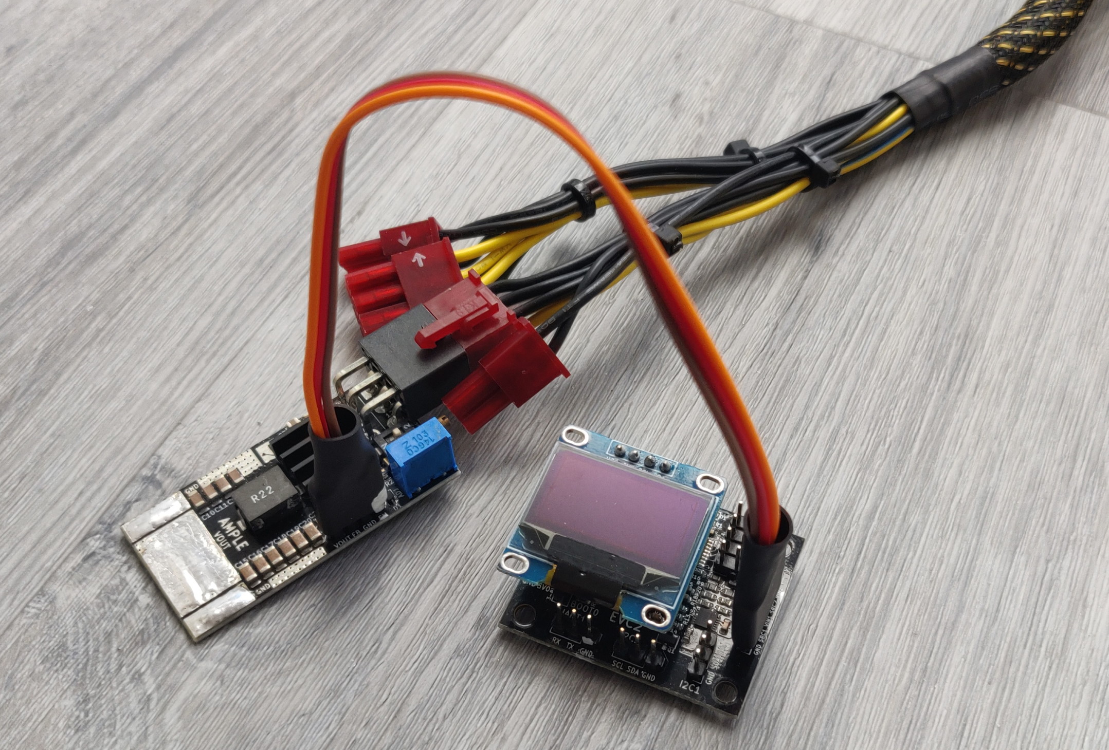
The ElmorLabs AMPLE 20A Power Card4 is a small single-phase external power board, which can provide one voltage from 1,000-3,400 mV with 20 A.
Normally you hook one of those boards onto a graphics card to power the memory externally. This is way more power than we need.
It is relatively cheep and small, so you don’t mess up your table, while overclocking.
You have two options to adjust the voltage of this board. Either you use a small screwdriver to alter it directly on the board, or use another piece of equipment from ElmorLabs.
The ElmorLabs EVC25 is a small board which has one header each for SPI, UART, VMOD and two for I2C. For the AMPLE you need the VMOD-header. Using the FB-pin (feedback) you can adjust the voltage-output.
I’ll write another article about how to use this piece of hardware, because you need to measure some resistors and use the EVC2-software.
EVGA EPOWER V
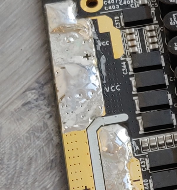
The EVGA EPOWER V6 is a 12+2 phase external power board, which can provide two separates voltages, one labeled VCC from 600-2,000 mV with 600 A and one labeled VMEM from 600-2,300 mV with 80 A.
This is total overkill for overclocking a Raspberry Pi. Normally use solder it onto high-end graphics cards from NVIDIA or AMD.
I wanted one, I got one, now I have to use it. Simple and plain…
Notice: If you look closely you find a 4-pin header right beside the buttons. This is a serial-header7, which can be used for controlling the EPOWER V.
Just use an EVC2 or another USB/Serial-adapter and PuTTY8 or your program of choice to get access to the menu for controlling the voltages.
Soldering iron
Just a quick notice: Use a good and powerful soldering iron, when you solder wires onto the external power boards. The big pads suck a lot of energy, so your 15 W iron won’t get the solder onto it.
I use an ERSA 150 S9 for the power boards.
While soldering with 150 W on the power boards is mostly harmless, the Raspberry Pi is quite small and the heat provided by this iron can be harmful.
A smaller iron with less power and a more pointy tip could be useful, or use great caution. It is possible.


